
Frequently asked questions regarding slope Measurement
What are the influences of acceleration forces on inclination sensor measurements, e.g. in vehicles?
Inclination measures the angle of the gravitational acceleration vector to the measuring object in a vertical plane. Any accelerations in other directions, e.g. horizontal (speeding up or braking) or centrifugal (driving along curves) result in a combined acceleration vector with a direction that deviates from gravitational acceleration alone. In these cases, the inclination sensor (independend of type or make) will respond to the resulting acceleration vector and exhibit a "measurement error". If the added acceleration is exactly perpendicular to the plane of measurement or if the plane of measurement is banked crosswise, i.e. turned around the cross-section of the horizontal and the measurement plane, this is, ideally, not registered. SEIKA N and NG inclinometers react to a bank of 45° with a measurement error below 1% of the measured value. SEIKA NB and B sensors are transverse acceleration insensitive.
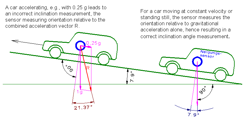
However, any acceleration in the measurement plane, i.e. the screen in the image above, that is not parallel to gravitational acceleration leads to measurement errors, regardless of the type of inclination sensor used.
What are possible ways out?
1. Because the gravitational acceleration is static (frequency zero) and the disturbing accelerations are often dynamic (frequency larger zero) one can potentially separate both by suitable low-pass filtering. A detailed consideration of the expected measuring dynamic and the frequency of the disturbing acceleration is necessary. The larger the difference between the measured frequency and the disturbing acceleration, the better both can be seperated. However, frequency filters cannot be realized with arbitrarily steep edge characteristics.
2. Perhaps one has to use much more expensive and complex giro systems, perhaps in combination with acceleration and/or inclination sensors, as is the case for inertial measurement units (IMU). However, also these systems have their own issues.
3. Measurements relative to an external reference system are also possible in a limited reference area.
In any event an exact analysis of the measurement problem is important.
Where should the inclination sensor be fastened on the item?
The most favorable attachment place is the pivot of the item!
Above or below the pivot more or less strong horizontal transverse accelerations occur that lead to measurement errors (see above). If the item is moving slowly (quasi-static measurement), i.e. the disturbing acceleration is negligible in relation to gravitational acceleration, the measurement error is correspondingly small or negligible.
Possible measuring errors due to angular acceleration of the item are avoidable by electrical interconnection of two inclination sensors that are fastened opposite to each other at equal distance from the pivot (one above and one below the pivot). The positive and negative measurement errors cancel each other out and the measurement value is doubled.
Also in this cases the exact analysis of the measuring problem is necessary.
Can one equate the resolution of a sensor with the measurement accuracy?
No! (Even if some manufacturers advertise with "infinite resolution" specifications or similar. This is nonsense.)
The resolution expresses the possible changes of the measured parameter. In most cases this refers to a signal change that is larger than an interference signal (electronic noise) and other error influences, e.g. hysteresis.
The resolution is important for the acquisition of small angular changes (swinging motion of a crane, a bridge etc. under dynamic load effect under essentially unchanged enviromental conditions like temperature, operating voltage etc.).
The measurement accuracy expresses the maximal deviation of the measured value from the real value under specific operating conditions. Because every measuring system depents on different influences, they have to be known to estimate measurement accuracy.
Information on errors from which one can calculate the accuracy are mostly listed in the data sheets. However, not all possible influences can be considered. In some extreme cases it may be necessary to conduct your own investigations into the accuracy of the sensor.
In most cases it is sufficent to consider the influence of temperature changes, the "main enemy of precision measurements". It is plausible that the measuring error under room conditions will be smaller than at an outdoor crane boom with the complete spectrum of automative temperature range or at a ram with extreme vibrations or in a nuclear installation in a high radiation environment.
Can an inclinometer be used to determine a direction on a horizontal plane?
No!
For that kind of work a compass is suitable. For this reason a triaxial inclinometer does not exist.
Are there error free sensors?
No!
Despite sophisticated electronics, advanced signal processing and constantly improving technical possibilities there are always measurement errors and some measurement requirements are impossible to fulfill, or rather require an adaptation of requirements or measurement conditions.
For this reasons a detailed analysis of the respective measuring task is always important.
What is the effective method of the SEIKA liquid based inclinometers?
The composition of the dielectric liquid guarantees an optimal temperature behaviour, high long term stability, hysteresis free measurements, minimal linearity errors and short response times among other properties. In connection with the sensor-integrated electronics there is a high electromagnetic compatibility.
What is the difference between a liquid-based inclinometer and an inclinometer on the basis of a spring-mass system?
A liquid-based inclinometer scans the horizon of a liquid. This can be done optically, resistively, magnetically or capacitively. Regardless of how the liquid is scanned, one important property is in common: the liquid level adjusts itself horizontally at different levels of gravitational acceleration, i.e. regardless of the exact value of the gravitational force. This enables, for example, accurate tilt measurements at different locations, regardless of whether the measuring point is on the equator or on the North Pole, on the seabed or on a high mountain, on the moon or on Mars.
An inclinometer with spring-mass system (e.g. all micromechanical inclinometers) scans the displacement of a mass on a spring. This displacement depends both on the spring constant of the measurement system and on the exact value of the gravitational acceleration at the location where the measurement is taken.
Varying gravitational accelerations therefore lead to varying displacements and corresponding differences in the measured inclination angle. For precise measurements such a sensor must be calibrated to the local gravitational acceleration and cannot be used universally.
A pendulum can also be used to measure inclination. A pendulum with zero restoring force behaves similarly to a liquid-based inclination sensor in regard to it's advantages relating to the influence of gravity.
A further advantage of liquid-based inclinometers is the unlimited measuring range, since there is no sinusodial relationship between inclination angle and output signal. Introducing a compensating measurement value correction for spring-mass sensors at large angles, as is practiced by some manufacturers, inevitable leads to increasing measurement errors at large angles.
At small angles of inclination and when calibrated against local gravitational acceleration, spring-mass systems can be favourable. Silicon based micromechanical spring-mass systems (MEMS) are limited in their measurement sensitivity and signal-to-noice ratio.
What are the differences between capacitive and resistive scanning of the liquid level in an inclinometer?
Liquid-based inclination sensors primarily employ resistive or capacitive methods.
Resistive scanning registers the change of resistance in a conductive liquid due to a varying contact area caused by changes in inclination.
Capacitive scanning registers the change in capacity when dielectric liquid fills more or less of the area between two condenser electrodes at different inclinations.
Resistive scanning of the liquid level is complicated by the boundary layer between the liquid and the measuring electrodes as well as problems due to electrolysis through current flow in the liquid that causes ageing. The temperature dependent resistivity of the conductive liquids further introduces comparatively high and often non-linear temperature drifts.
Such issues do not occur with capacitively scanned dielectric liquids, where aging and non-linear temperature drifts are not inherent. The former disadvantage of more complex electronics no longer plays a role today, when the necessary signal processing can easily be integrated on silicon chips.
Can measurement errors be corrected computationally?
Yes! But unfortunately not all.
All systematic errors can be corrected for in principle, which to a large degree is already realized in the sensor. The temperature drift of the primary transformer due to the temperature dependency of the liquid's dielectric constant is corrected for in most SEIKA inclinometers, as is any production variation of the primary transformer.
Stochastic errors cannot be corrected, i.e. random variations in the measuring signal caused by, e.g., electronic noise. Such errors often are the limits of what is possible.