B1, B2, B3
Accelerometers of high overload resistance with integrated electronics for measurement of acceleration in the frequency range 0 to several 100 Hz
Features
- very high overload resistance
- lower cut-off frequency is zero, hence suitable for measuring static acceleration, such as gravity (inclinations) or radial acceleration (centrifugal force)
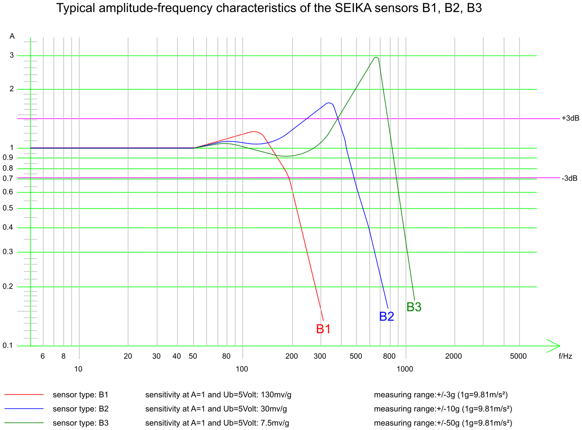
- linear frequency response with little or no resonant peak at upper cut-off frequency
- low total harmonic distortion
- high signal-to-noise ratio
- no measurable hysteresis of signal
- hermetically sealed
- high long-term stability
- small temperature drift
- integrated sensor electronics
- analog DC or pulse width modulated or frequency modulated output
- low power consumption
- very short on-transition delay
- optional galvanic isolation of sensor circuit from measuring location
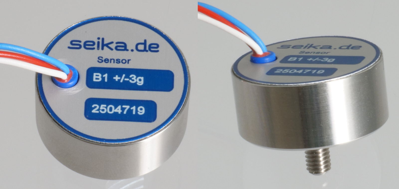
- multiple housing options – M4 thread (default), M3 thread, magnetic housing, special requests
Description
The sensors B1, B2 and B3 are capacitive spring-mass accelerometers with integrated electronics. Resonant peaks are minimized by special gas-dynamic damping in the primary transformer.
The sensors are manufactured with an analog DC output. The sensor electronics require only small amounts of power and are in conjunction with the capacitive primary transformer characterized by low error and high long-term stability.
Application
The accelerometers B1, B2 and B3 are used for applications requiring high overload tolerance, high long-term stability, small lower cut-off frequency down to measurement of static acceleration, very short on-transition delay and low power consumption. Typical applications include:
- measurements on vehicles, machinery, buildings and plants for process control and error diagnosis
- seismic measurements
- inclination measurements
- safety engineering
- dynamic measurement of position and velocity
Specifications
| Type | B1 | B2 | B3 |
|---|---|---|---|
| Measuring range | ±3g (ca.±30m/s2) | ±10g (ca.±100m/s2) | ±50g (ca.±500m/s2) |
| Resolution | <10-3g | <5·10-3g | <2·10-2g |
| Frequency range | 0...160Hz | 0...350Hz | 0...550Hz |
| Values for analog DC output at UbN = 5 Volt | |||
| Sensitivity | approx. 130mV/g | approx. 30mV/g | approx. 7.5mV/g |
| Temperature drift of sensitivity | approx. +0.051%/K | approx. +0.035%/K | approx. +0.026%/K |
| Temperature drift of zero point | approx. ±0.1mV/K | approx. ±0.1mV/K | approx. ±0.1mV/K |
| Type | B1 |
|---|---|
| Measuring range | ±3g (ca.±30m/s2) |
| Resolution | <10-3g |
| Frequency range | 0...160Hz |
| Values for analog DC output at UbN = 5 Volt | |
| Sensitivity | approx. 130mV/g |
| Temperature drift of sensitivity | approx. +0.051%/K |
| Temperature drift of zero point | approx. ±0.1mV/K |
| Type | B2 |
|---|---|
| Measuring range | ±10g (ca.±100m/s2) |
| Resolution | <5·10-3g |
| Frequency range | 0...350Hz |
| Values for analog DC output at UbN = 5 Volt | |
| Sensitivity | approx. 30mV/g |
| Temperature drift of sensitivity | approx. +0.035%/K |
| Temperature drift of zero point | approx. ±0.1mV/K |
| Type | B3 |
|---|---|
| Measuring range | ±50g (ca.±500m/s2) |
| Resolution | <2·10-2g |
| Frequency range | 0...550Hz |
| Values for analog DC output at UbN = 5 Volt | |
| Sensitivity | approx. 7.5mV/g |
| Temperature drift of sensitivity | approx. +0.026%/K |
| Temperature drift of zero point | approx. ±0.1mV/K |
| Shared specifications | |
|---|---|
| Linearity deviation | <0,5% |
| Transverse sensitivity | <1% |
| Mechanical overload resistance in direction of measurement | 10 000 g (approx. 100 000 m/s2) |
| Nominal supply voltage (regulated externally) | UbN = 5 Volt |
| Permissible range of supply voltage | Ubz = 3V ... 6V |
| Current drawn at Ub = 5V | approx.1mA |
| Degree of protection | IP65 |
| Operating temperature | -40°C ... +85°C (125°C optional) |
| Storage temperature | -45°C ... +90°C (125°C optional) |
| Weight (standard housing with approx. 18cm wires) | approx. 26g |
| Electrical connection | standard: • 3 highly flexible, color-coded wires ø ~1mm, length approx. 18 cm optional: • 0.5m strong, flexible, shielded cable, 2 wires + shield, ø2,1mm or • 3 flexible, color-coded wires with Teflon insulation for extended temperature range • special lengths on request |
| Values for analog DC output at UbN = 5 Volt | |
| Zero offset at Ub=5V | 2.5±0.1 Volt - generally: 0.5Ub±4% |
| Output impedance | 10 kOhm |
- • Each sensor is calibrated after production. It is delivered with an individual calibration record that includes the precise offset and sensitivity values, the static characteristic curve and the linearity deviation curve.
- • On request: PWM-output
Dimensions (in mm) and Connections

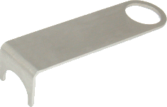
Accessory MAGZ1 — lever to detach the magnetic housing
Frequency response