Sensorbox containing one highly sensitive servo inclinometer and one signal conditioner with ±4 Volt or 0.5 ... 4.5 Volt output
Features
- small measuring range of max. ±1° with extremely high resolution through use of a SEIKA servo inclinometer
- integrated signal conditioner with symmetrical ±4 Volt output for long transmission lines and minimal interference susceptibility
- robust pressure die cast aluminium housing (IP67) with saltwater proof coating
- 12 Volt or 24 Volt supply voltage
- the SBS1U output signal is calibrated to customer's specifications
- sensor and signal conditioner electrically isolated from housing
- extensive EMC protection
- highly stable sensor voltage supply
- either connection polarity
- high mechanical overload resistance
- low pass filter with optional choice of cut-off frequency for suppression of interference frequencies
Description
The SBS1U is a pressure die cast aluminium sensor housing (IP67) with an integrated sensor for highly sensitive, uniaxial acceleration or inclination measurements.
As well as the sensor, the housing contains a signal conditioner with ±4 Volt output and a separate, highly stable voltage supply. Furthermore, the signal conditioner includes active low pass filters for suppression of interference signals and transient suppression for EMC guarantee. Interference signals caused by unwanted ground currents are eliminated by electrically isolating sensor and signal conditioner from the housing. The terminals provide either two mutually inverse asymmetric 0.5 ... 4.5 Volt or one symmetrical ±4 Volt output voltages.
The compact metal cable gland and small housing size in combination with the max. 6-wire connection enable the use of this high quality measuring system in harsh operating conditions.
Application
The SBS1U is suitable for applications requiring extremely precise inclination measurements under harsh operating conditions and an analog signal output. Typical areas of successful application include stability monitoring of buildings and machinery and inclination monitoring on bridges, dams, towers, tunnels, slopes and structures in danger of collapse or earthquakes.
Specifications
| Terminals | 6 x 1.5mm2 |
| Cable gland | M12 x 1.5, metal cable gland with integrated strain relief, clamping range 6mm ... 7.5mm |
| Measuring range | max. ±1 degree , smaller ranges optional |
| Resolution | 0.01 arc seconds = 48µm/km! |
| Degree of protection | IP67 |
| Mounting orientation | wall mounting; see drawing (standard: cable down) |
| Torque housing lid | 1.5Nm |
| Supply voltage optional | 12 Volt oder 24 Volt (±10%) |
| Operating current | max. 100mA |
| Normalized asymmetric output voltage range (GND...Ua+) | 0.5V ... 4.5V |
| Normalized asymmetric output voltage range (GND...Ua-) | 4.5V ... 0.5V |
| Normalized symmetric output voltage range (Ua-...Ua+) | -4V ... +4V |
| Asymmetric zero output voltage (GND...Ua+) | 2.5 Volt |
| Asymmetric zero output voltage (GND...Ua-) | 2.5 Volt |
| Symmetric zero output voltage (Ua-...Ua+) | 0 Volt |
| Output impedance | approx. 100 Ohm |
| Recommended cable | see drawing |
| Cable length taking voltage drop due to the operating current into account | any (e.g. 500m for 12V or 1km for 15V voltage supply and using the recommended or equivalent cable) |
| Capacitive output loading capacity | any |
| Resistive output loading capacity | greater than 100 kOhm |
| Output driver | operational amplifier TLC2274 |
| Adjustable variable | amplification |
| Signal rise time (to 98% of step input) | approx. 2 seconds |
| Step input response | PT2 behaviour |
| Operating temperature | -40°C ... +85°C |
| Mechanical angle adjustment range | ±2° |
| Weight | approx. 420g |
- • The box is delivered with an individual calibration record that includes the precise offset and sensitivity values, the static characteristic curve and the linearity deviation curve.
Options:
- • special measuring ranges • silicon encapsulation • custom wiring
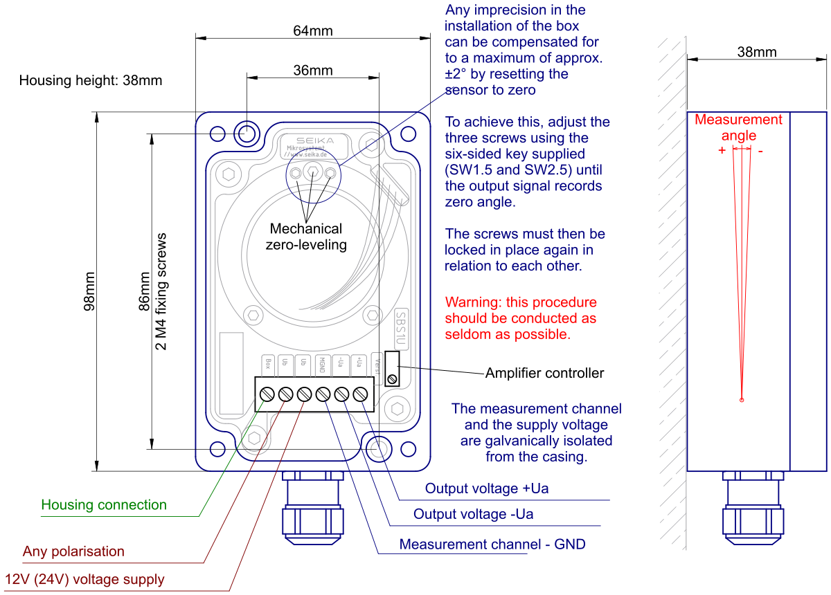
 3D geometry as STEP file
Dimensions (in mm)
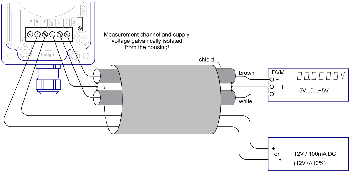
Connections