 [+] [+] |
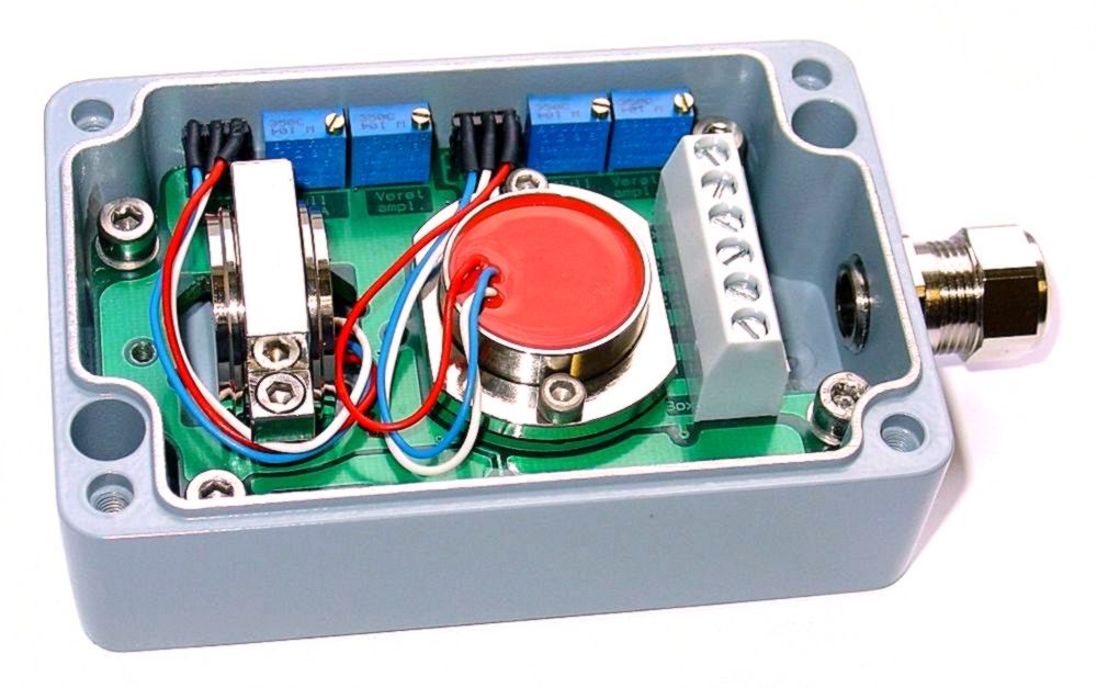
| SB2I Sensor box containing two sensors and two signal conditioners with 4...20mA, 2-wire outputs |
Features
Description
The SB2I is a
pressure die cast aluminium sensor housing (IP67) with two
integrated sensors for measuring inclinations and/or
accelerations along two axis.
As well as the sensors, the box contains two independent signal
conditioners, each with a 4...20mA, 2-wire output, and two
separate, highly stable voltage supply feeding off the
corresponding current loop, one for each sensor. Furthermore,
each signal conditioner includes an active low pass filter, whose
upper cut-off frequency / settling time can be adjusted to suit
the measurement task, an output stage with current limitation, a
noise voltage filter and a diode bridge for unipolar connection
to the current loop. Interference signals caused by unwanted
ground currents are eliminated by electrically isolating each
sensor and signal conditioner from each other and the housing.
A special electronic temperature compensation system can
significantly reduce the temperature sensitivity of the
implemented sensors. The compact PG cable gland and small housing
size in combination with the 3-wire connection enable the use of
this high quality measuring system in harsh operating conditions.
Application
The SB2I is suitable for applications requiring precise inclination or acceleration measurements along two axis under harsh circumstances and returning of a 4...20mA output signal each. Areas of successful implementation include construction, mining, agricultural machinery, transportation and conveyor systems, ships, operation and automation technology as well as general mechanical engineering.
Technical Specifications
| Terminals | max.: 6 x 1,5 mm2 |
| Cable fixing | M12 x 1.5 cable gland, clamping range 6mm ... 7.5mm |
| Measuring range, Resolution, etc. | dependents on implemented SEIKA sensors |
| Degree of protection | IP67 |
| Mounting orientation | any |
| Measuring planes (N.. sensors) | 3 main housing planes |
| Measuring directions (B.., BD.. sensors) | in X,Y,Z coordinate of housing |
| Terminal voltage | 10V ... 30V |
| Minimum loop currents | 2.5mA ... 3.5mA |
| Maximum loop currents | 22mA ... 26mA |
| Output signal loop current | 4mA ... 20mA (12mA for zero position) |
| Adjustable variables | zero point (12mA), amplification |
| Maximum load resistances | 500_Ohm (at 24 Volt supply voltage) |
| Low pass filter | active, 3rd order, minimal ripple |
| Operating temperature | -40...+85°C |
Options: special measuring ranges, calibration record, silicon encapsulation, custom wiring
Dimensions (in mm)
|
Block Diagram
|
Connections
|
SEIKA Mikrosystemtechnik GmbH - Söllerweg1- D 87487 Wiggensbach - email: seika@seika.de - Tel.+49 8370 9290070 - FAX:+49 8370 9290079
H118S