 [+] [+] |
| NG360 Inclinometer with digital RS485 communications port and 360 degree measuring range |
Features
Description
The NG360 is a
capacitive, liquid based inclinometer with integrated sensor
electronics and 16 bit microprocessor. The measurement result is
transmitted via a RS485 port for further processing. Up to 78
sensors can be operated using a single communications line.
The measurement method provides a linear relationship between the
angle to be measured and the output signal. The determined angle
is independent of the local gravitational acceleration, that
means that no matter where the measurement is being taken,
whether in Europe, Australia, on Mount Everest or on the moon,
the inclination will be measured correctly anywhere. Temperature
related inaccuracies are corrected by the integrated
microprocessor.
Application
The NG360
inclinometer is suitable for applications requiring the
measurement of any angle for further processing on a PC.
Typical areas of application include construction, mining,
vehicles, aircraft, ships, surveying equipment, and
transportation and conveyor systems.
Technical Specifications
| Type | NG360 |
| Measuring range | 360 degrees |
| Resolution | 0.01 degrees |
| Dimensions | see dimension drawing |
| Linearity deviation | ±0.25 degrees |
| Transverse sensitivity | < ±0.1 degree at 45° tilt |
| Settling time | approx. 0.3 seconds |
| Supply voltage UbN | 9V ... 15V |
| Supply voltage on-transition time | < 50ms |
| Current drawn | approx. 30mA |
| Degree of protection | IP65 |
| Operating temperature | -40 bis +85°C |
| Storage temperature | -45 bis +90°C |
| Weight (without clamping ring or cable) | approx. 110 grams |
| Electrical connection | 2m shielded cable Ø 4.6 mm |
NG360 sensor connection to RS485 bus
|
Connection to SEIKA RS232/RS485 converter SC485B
|
Dimensions (in mm)
|
Data transmission protocol of measured angle
Step |
PC transmits | Sensor transmits | |
| 1. | Adress (e.g. B1 or B2 or B3...) |
||
| 2. | ENQ (05h) | ||
| 3. | 15ms pause (switching from receive to transmit in sensor) | ||
| 4. | STX (02h) e.g.: 359.99 (angle in ASCII code) ETB (17h) |
||
| 5. | Checksum (2 Byte ASCII code) $ (24h) |
The checksum is the XOR combination of the sensor output in step 4 (e.g. 02h XOR 359.99 XOR 17h) | |
| 6. | 15ms pause (switching from transmit to receive in sensor) | ||
| 7. | ACK (06h) if checksum is correct NAK (15h) if checksum is wrong |
||
| 8. | If ACK, terminate If NAK, return to 3. |
||
PC COM port settings for the RS232/RS485 converter
| Bit/Sec | 9600 |
| Data bit | 8 |
| Parity | none |
| Stop bit | 1 |
| Protocol | none |
Software (Windows 95 - Windows 11)
To
display the measurement results and configure the sensor the
following programs are used. These programs require a PC running
Windows 95/98 up to Windows 11.
Although the NG360 will operate from any half-duplex RS485 port,
we recommend using the SEIKA interface converter SC485B.
NG360 programs should be copied to the harddrive before running
them!
GetAngle.exe [ load program ] [GetAngle.zip](V.2023.10)
This program displays the angle of one or more NG360, which are connected through a RS232/RS485-Converter (i.e. SEIKA SC485B) to the PC. The serial port COM.., the sensor address and the display speed (averaging of several measurements) can be adjusted. Additionaly, measurements can be saved to a logfile in regular time-intervals, for further processing i.e. with MS Excel.
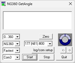
If
more than one sensor is connected to the same bus, the address
177 (hB1) #00 (as in the figure above) must not be used!!!
Since they always respond to the base address 177 (hB1), all the
sensors would then answer simultaneously, inevitably causing
jamming on the data bus and preventing the transfer of useful
information.
Nevertheless, the address 177 (hB1) may be used if only one
sensor is active.
NG360Setup.exe [ load program ](V.2023.10)
This program can be used to change several
parameters of the NG360. These parameters can be read, modified
and then saved permanently in the NG360 EEPROM. This does not
affect any calibration values.
Attention! If more then one NG360 are configured to use the same
address, this inevitably leads to a bus conflict and may damage
the bus-driver IC! Reprogramming of the addresses will then only
be possible, if every but one sensor on the bus is switched off.
Every sensor responds to the address 177 (hB1), and therefore no
NG360 sensor should be programmed to use this address. Addressing
a NG360 individually on a bus with multiple active NG360s is
impossible after writing address 177 (hB1) to it. As all sensors
always respond to the base address 177 (hB1), the transmitted
data would be stored in all sensors, deleting any previous
settings, in particular the individual addresses. The latter
would then have to be reprogrammed.
If only one sensor is active, then the address 177 (hB1) can be
used, necessary if the sensor's individual address isn't known or
hasn't been assigned yet.
After that, invoking "read variables"
returns the desired sensor's current configuration and displays
the values in the corresponding boxes.
After selecting the values for the sensor variables V024, V025,
V026 and V063 from their menus, clicking "write
variables" permanently writes them to the addressed sensor's
EEPROM.
The variable V064 (delay for serial port) determines the time
period between the data bytes sent by the sensor. The standard
setting is 500 and the value may be increased to ensure reliable
data transfer for slow PC serial ports.
For applications requiring fast measurements, the signal
filtering may be turned off by setting V025 (order of the filter)
to 0 (no filter). However, these measurements tend to be more
unstable. Slow measurements using a 2nd order filter with a low
cut-off frequency (V026) display more stable measurement results.
Only one program (GetAngle.exe or NG360Setup.exe) may access the
serial port at any one time, although more than one may be
running simultaneously.
Any program using the above communication protocol will work with
the NG360 sensors.
NG360Scan.exe [ load program ](V.2023.10)
You can use this program to identify every NG360 sensor connected to a serial PC COM port through a RS232/RS485-Converter. The program scans the whole range of possible NG360 addresses and displays the angle values send by each connected sensor.
Invoking
"Scan" makes the program request a reading from each of
the possible 78 addresses and wait for a response. Should a
sensor respond, then the received angle measurement is displayed
above the address.
After completing the scan, all active sensors can be determined
by inspection.
Clicking the "Start reading" button causes the program
to continually request and display the current angle for every
active sensor connected to the bus until terminated by clicking
"Stop reading".
NG360Example.exe [ load source ](V.2017.1)
This directory contains an example program for programmers, with complete MS Visual C++ sourcecode. This open source example program developed using MS Visual C++ 5.0 provides some information how to develop interface software for the RS232/RS485 converter and the NG360 sensors.
Hardware-RESET
Upon activation of the supply voltage, the NG360
inclinometer is forced into a predefined operating state by a
RESET. This procedure is important for a correct functionality of
the internal microprocessor. The supply voltage rise time must be
as short as possible for the RESET to be successful.
A slow supply voltage rise time or switching the sensor on, off
and on again in quick succession (bouncing) can cause the
programs running on the internal microprocessor to crash, giving
the impression of a defective sensor. Switching the supply
voltage on correctly will start the sensor up again correctly.
Similar problems can occur if the supply voltage falls below 9V
or fluctuates around 9V.
The operational time for a correct supply voltage is unlimited.
SEIKA Mikrosystemtechnik GmbH - Söllerweg1- D 87487 Wiggensbach - email: seika@seika.de - Tel.+49 8370 9290070 - FAX:+49 8370 9290079
H118S